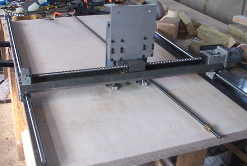
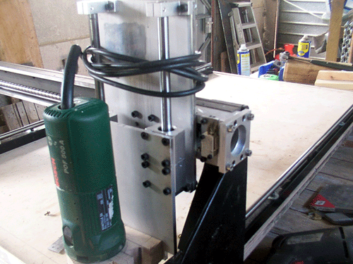
I have put the X 
 Y and Z
axis on the table they slide ok I still need the
trapezoidal screw to be milled down at the ends to take some bearings for the Z axis this I can not do my self i don't have the tools and it need to be right
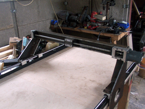
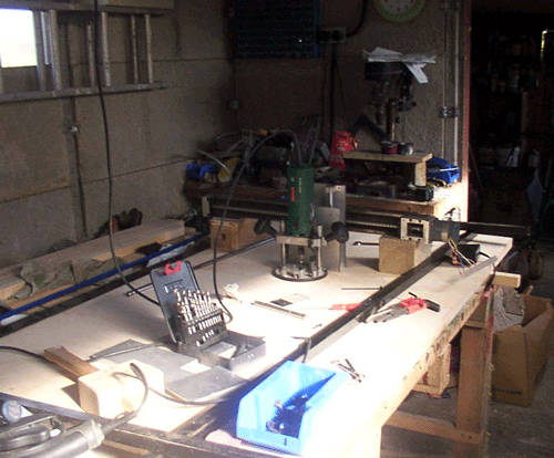
I have started by getting some of the parts for my cnc mill the base is a 30mm sheet of  ply 1200mm by 600mm
and you can see from the photo I had some luck with the Y axis I did a deal with someone.  they had a
5mm pitch ball screw assembly unit on a THK rail with a stepper motor. which was a good  starting point for the mill I have also started to make the Z axis from a sheet of aluminum and some steel rod you can just see next to the router


I have  fixed  the Z axis to the Y axis and cut a 150mm bit  of the trapezoidal screw. I will get 1000mm off travel on the X axis and it should give me 150mm travel on the Z axis. it needs to have the ends milled down to fit the bearings I don't know how
I am  going to do this
I might have to get this done bye some one. I also need some blocks made for the ends and the nut


the control panel


here I am just laying out the parts. its just to see how they will fit on the table. the round rails are 12mm hardened polished steel which will run on 4 open linear bearing carriers which I got from ebay. I also got from ebay was the 1500mm long trapezoidal screw with 3 nuts. you can see the Z axis witch i have made its just stood by the Y axis unit i got

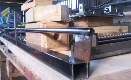
this is the round rails it is not bent it just looks like that in the photo I had a problem I could not drill the rod it was to hard. to get someone to drill and tap the rails  they would have cost  £60 each
so I welded some tabs to the rails

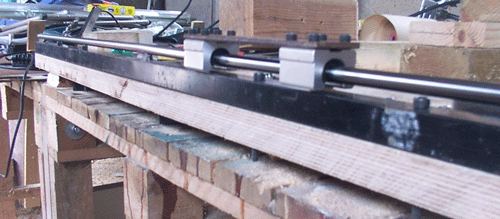
you can see in the photo how the rails should work I hope they will take the wait of the Z axis.
the rail is on 20mm by 20mm box steel I will have to see how this works I think the ply bed might bend in the middle to with all this wait  

for some reason i did not take any photos off the parts for the sides of the  gantry I made for the Z axis I think is was because they are just some bits of metal cut out of a 5mm sheet of steel and welded they did not look all that existing so I did not take any photos. they did take a long time to cut out  with a jigsaw.
it seems to work well I cut a hole in the side to keep the wait down
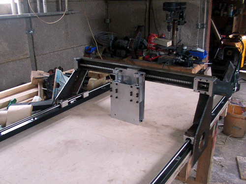
I have made a test  clamp out off ply for the router its not all that nice looking but it dose show me how it will work.
I also have put some micro switch's on the y
axis this was not essay to find some where to put them with out them getting in the way  
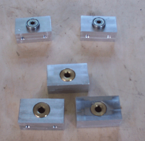
I have had some blocks made for the nuts and bearings for the axis which I could not make  ( what I need is a cnc mill )
I could have made them bye hand but they would need to be done right to make them work with the lead screws for the X and Z axis